ZIYUAN

Enquiry
0
INQUIRY

 English
-
 English
 -
Français
-
한국어
-
日本語
-
IndonesiaName
-
Polski
-
Deutsch
-
Português
-
Español
-
Tiếng Việt


Send Your Inquiry Today
Thanks for Your Inquiry, We will Get back to You within 8 Working Hours!
Video Introduction of Ziyuan
Showcases Ziyuan’s company/factories & solar mounts: Balcony, Rail, etc. + manufacturing.
Invitation Letter
The Definitive Engineer's Guide to Solar Panel Mounting Clamps
“
Discover everything about solar panel mounting clamps in our expert guide. Learn the difference between mid and end clamps, material selection, torque specs, and installation best practices.
”
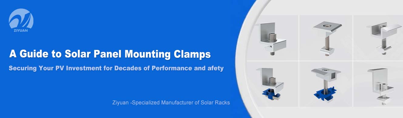
Table of Contents
Introduction: The Critical Connection
Section 1: Foundational Components: Understanding Mid Clamps vs. End Clamps
1.1. The Role of the Mid Clamp: Securing the Array's Core
1.2. The Role of the End Clamp: Protecting the Perimeter
1.3. At a Glance: A Functional Comparison
Section 2: Material Science in Focus: Selecting the Right Alloy for Maximum Durability
2.1. The Industry Standard: Anodized Aluminum
2.2. The Premium Choice: Stainless Steel
2.3. The Niche Application: Galvanized Steel
2.4. Material Selection Matrix
Section 3: The Engineer's Specification Guide: Ensuring Perfect Compatibility and Fit
3.1. Match the Clamp to the Module Frame Height
3.2. The Rise of Universal Clamps
3.3. Clamping Frameless (Glass-on-Glass) Modules
Section 4: A World of Applications: An Overview of Specialized Solar Clamps
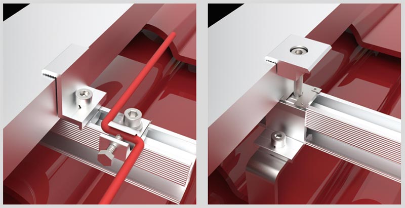
4.1. For Metal Roofs: Non-Penetrating Standing Seam Clamps
4.2. For Profiled Roofs: Trapezoidal & Corrugated Clamps
4.3. For Enhanced Security: Anti-Theft Clamps
4.4. For System Safety: Grounding Clamps and Bonding Washers (WEEBs)
Section 5: Precision Installation: Torque, Tools, and Technique
5.1. The Critical Role of Torque: A Delicate Balance
5.2. Adhering to Manufacturer Specifications
5.3. The Essential Tool: The Calibrated Torque Wrench
5.4. A Step-by-Step Installation Guide
Section 6: Advanced Structural Considerations: Mastering Solar Panel Clamping Zones
6.1. Defining the Zones: Green, Yellow, and Red
6.2. The Critical Link to Warranty and Performance
Section 7: Long-Term Reliability: Maintenance, Inspection, and Troubleshooting
7.1. Routine Inspection Checklist
7.3. Troubleshooting Common Failures
Section 8: The Hallmark of Quality: Understanding Industry Standards & Certifications
8.1. The North American Benchmark: UL 2703
8.2. International Standards: TÜV Rheinland and IEC
Conclusion: Securing Your Solar Investment from the Ground Up
Introduction: The Critical Connection: Why Solar Panel Clamps are the Unsung Heroes of PV System Longevity
In the architecture of a photovoltaic (PV) installation, while solar panels and inverters capture the spotlight, the long-term performance, safety, and bankability of the entire system rest upon a series of small, meticulously engineered components: the mounting clamps.[1] These are not mere fasteners; they are the critical interface that physically secures the PV modules to the mounting structure, transferring immense and dynamic structural loads for the 25-plus year lifespan of the system.[1, 2] As the unsung heroes of any solar array, these clamps are the first line of defense against a relentless barrage of environmental forces, including wind uplift, snow load, and the constant cycle of thermal expansion and contraction.[2, 3, 4]
The structural integrity of a multi-million-dollar solar asset can be compromised by the failure of a single, poorly chosen or improperly installed clamp. Such a failure can cascade into catastrophic consequences, from panel misalignment and reduced energy output to complete panel dislodgement, causing significant damage to roofing materials and posing a severe safety hazard.[2, 5, 6] Consequently, a deep, technical understanding of solar panel mounting clamps is not an ancillary detail but a fundamental prerequisite for engineers, project developers, and installers committed to building durable and reliable solar energy systems.
This guide provides a comprehensive engineering overview of solar panel mounting clamps. It moves from foundational principles—distinguishing the core clamp typologies and their material science—to advanced practical considerations, including specialized applications, precision installation techniques, the critical nature of module clamping zones, and the international standards that govern their quality and safety. This analysis will equip industry professionals with the expertise needed to specify, install, and maintain the vital connections that secure their solar investments for decades to come.
Section 1: Foundational Components: Understanding Mid Clamps vs. End Clamps
At the heart of every conventional solar array are two primary types of clamps that work in concert to create a secure and stable matrix of panels: the mid clamp and the end clamp.[1] While they may appear similar, their design, function, and placement are distinct and purpose-engineered to manage different structural loads across the PV array.
1.1. The Role of the Mid Clamp: Securing the Array's Core
The mid clamp, also referred to as a middle clamp or inter clamp, is the workhorse of the solar mounting system.[4, 7] Its primary function is to be positioned in the gap between two adjacent solar panels, securing both modules to the mounting rail simultaneously.[1, 8, 9] By doing so, mid clamps create a unified and structurally interconnected array, ensuring precise and consistent spacing between panels.[4, 10]
The design of a mid clamp is characteristically symmetrical. It features a two-sided profile, often described as having two "steps," "lips," or ledges.[1, 2, 4] This dual-sided design is crucial as it allows the clamp to apply equal and evenly distributed pressure to the frames of both adjacent modules.[1] This uniform pressure distribution is a critical engineering feature that prevents the creation of concentrated stress points on the panel frames. Such stress points can lead to the formation of invisible microcracks in the delicate solar cells, which can significantly degrade the panel's performance and shorten its operational lifespan over time.[4] In any given solar array, mid clamps are the most numerous clamping component, with one required at every junction between panels along a single row.[1, 10]
1.2. The Role of the End Clamp: Protecting the Perimeter
The end clamp serves a specialized but equally critical function: securing the perimeter of the solar array.[1] These clamps are installed at the very beginning and the very end of each row of panels, fastening the outermost module to the mounting rail.[5, 8, 11] In essence, they "cap off" the row, preventing any lateral shifting of the panels and providing the primary structural defense against environmental loads, particularly wind uplift.[2, 12]
Unlike the mid clamp, the end clamp has an asymmetrical, one-sided design.[1, 2] It features only a single "step" or "lip" that presses down on the frame of the final solar panel in a row.[1] The outer edge of an end clamp is typically designed to be flush or smoothly rounded, contributing to a clean, finished aesthetic for the completed array.[1] While their aesthetic contribution is notable, their structural role is paramount. The edges and corners of a solar array are the areas most exposed to aerodynamic forces. Wind flowing over the array creates a low-pressure zone, generating significant uplift forces that are strongest at the perimeter. The end clamp is specifically engineered to counteract these forces, anchoring the most vulnerable part of the array firmly to the substructure.[1, 5] Regardless of the number of panels in a given row, exactly two end clamps are required: one at the start and one at the finish.[10, 12]
1.3. At a Glance: A Functional Comparison
The distinct roles of mid and end clamps are fundamental to proper system design and installation. A side-by-side comparison clarifies their specific functions and applications.
| Feature | Mid Clamp | End Clamp |
|---|---|---|
| Primary Function | Connects adjacent panels to each other and to the mounting rail, creating a unified array. | Secures the outermost panels in a row to the mounting rail, protecting the array's perimeter. |
| Placement | Positioned in the space between two adjacent solar panels within a row. | Positioned at the beginning and the end of each row of solar panels. |
| Design | Symmetrical and two-sided, with two "lips" or "steps" to secure two panel frames simultaneously. | Asymmetrical and one-sided, with a single "lip" or "step" to secure one panel frame. |
| Quantity per Row | One less than the total number of panels in the row (N-1). | Always two per row, regardless of the number of panels. |
Table 1: A functional comparison of mid clamps and end clamps, synthesized from data in [1] and.[2]
The distinction between these two components goes beyond their physical location; it is rooted in the different types of structural stress they are engineered to manage. Mid clamps are primarily designed to handle the compressive and shear forces that exist within the body of the array, maintaining the rigid alignment and spacing of the panels. End clamps, by contrast, are engineered to resist the tensile and uplift forces generated by wind. This aerodynamic lift is most powerful at the leading edges and corners of the array, making the end clamp's role not just one of termination but of critical defense against the most significant structural threat to the system's integrity.[1, 5]
Section 2: Material Science in Focus: Selecting the Right Alloy for Maximum Durability
The material composition of a solar panel clamp is the primary determinant of its strength, longevity, and ability to withstand decades of exposure to harsh environmental conditions.[1, 3] The choice of material is a critical engineering decision that directly impacts the long-term reliability of the entire mounting system. The industry has largely standardized around three core materials, each with a distinct profile of performance, cost, and application suitability.
2.1. The Industry Standard: Anodized Aluminum (e.g., 6005-T5)
Extruded aluminum alloy, particularly grades like 6005-T5, is the dominant material for high-quality solar clamps.[2] Its widespread adoption is due to an exceptional balance of desirable properties. It is strong yet lightweight, which reduces the overall structural load on the roof and makes the components easier to transport and handle during installation, often accelerating project timelines.[1, 13]
Crucially, aluminum is inherently corrosion-resistant. It naturally forms a passive, protective layer of aluminum oxide on its surface when exposed to air, which prevents rust.[1] This protection is significantly enhanced through a process called anodization, where the aluminum is submerged in an electrolytic bath to create a much thicker, harder, and more durable oxide layer.[12, 14] This makes anodized aluminum clamps an excellent choice for the vast majority of residential and commercial projects, particularly in regions with mild to moderate weather conditions.[3, 5]
2.2. The Premium Choice: Stainless Steel (e.g., SUS304)
For installations in aggressive and highly corrosive environments, stainless steel (often grade SUS304 or similar) is the material of choice.[2, 5] Stainless steel offers superior strength and unparalleled resistance to corrosion, making it indispensable for projects in coastal areas with constant saltwater spray, industrial zones with high levels of chemical pollutants, or any location subject to extreme weather.[5, 11, 13]
While it provides the ultimate in long-term reliability, stainless steel is also denser and more expensive than aluminum.[3, 5] Because of this, a common and effective engineering practice is to use a hybrid approach: aluminum is used for the main body of the clamp to keep weight and cost down, while stainless steel is used for the critical fastening hardware—the bolts, nuts, and washers—which require maximum strength and corrosion resistance at the point of connection.[2]
2.3. The Niche Application: Galvanized Steel
Galvanized steel represents a cost-effective alternative, primarily used in specific applications.[11] This material consists of a steel base that has been coated with a layer of zinc to protect it from corrosion. It offers good strength and is less expensive than aluminum or stainless steel, making it a viable option for large-scale, ground-mounted solar farms where budget is a primary driver and the higher weight of the components is not a structural concern for a rooftop.[11] However, the durability of galvanized steel is entirely dependent on the integrity of its zinc coating. If the coating is scratched or compromised during installation or over time, the underlying steel can be exposed to moisture and will begin to rust, potentially leading to premature failure.[3]
2.4. Material Selection Matrix
Choosing the optimal material requires balancing performance characteristics against the specific environmental challenges of the installation site and the project's budget.
| Material | Corrosion Resistance | Weight | Strength-to-Weight Ratio | Cost | Recommended Environments |
|---|---|---|---|---|---|
| Anodized Aluminum (6005-T5) | Excellent | Low | High | Moderate | Residential and commercial projects in mild to moderate climates. |
| Stainless Steel (SUS304) | Superior | High | Moderate | High | Harsh environments: coastal (salt spray), industrial (pollution), extreme weather. |
| Galvanized Steel | Good (if coating is intact) | High | Low | Low | Cost-sensitive, large-scale ground-mounted systems. |
Table 2: A comparative matrix of performance characteristics for common solar clamp materials, synthesized from data in [1, 3, 5, 11], and.[13]
The selection of a material involves more than just its individual properties; it requires consideration of its interaction with other components in the system. When two different metals, such as a stainless steel bolt and an aluminum rail, are in direct contact in the presence of moisture (an electrolyte), a phenomenon known as galvanic corrosion can occur.[15] In this electrochemical process, the more active (less noble) metal corrodes at an accelerated rate. This can lead to the rapid degradation and failure of connection points, even if the individual components are of high quality. Therefore, a properly engineered mounting system must be designed with galvanic compatibility in mind, either by using materials that are close together in the galvanic series or by incorporating non-conductive isolators between dissimilar metals. This system-level approach to material science is essential for preventing hidden, long-term failure modes and ensuring the structural longevity of the installation.[15, 16]
Section 3: The Engineer's Specification Guide: Ensuring Perfect Compatibility and Fit
Properly specifying solar panel clamps is a matter of precision. A mismatch between the clamp and the other system components can introduce stress, create instability, and ultimately compromise the entire installation. True compatibility is a multi-faceted requirement that extends from the panel frame to the mounting rail and beyond.
3.1. The First Commandment: Match the Clamp to the Module Frame Height
One of the most frequent yet entirely preventable errors in solar installation is the failure to match the clamp size to the height of the solar panel's frame.[1] Unlike many other industrial components, solar panel frame dimensions are not universally standardized. The frame height, or thickness, typically varies between 30 mm and 50 mm depending on the module manufacturer and model.[2, 12, 14]
The consequences of a size mismatch are severe. Using a clamp designed for a larger frame (e.g., a 40 mm clamp on a 35 mm panel) will result in a loose, insecure fit. This gap allows the panel to vibrate under wind load, which can lead to loosening of the fasteners over time and potential panel dislodgement.[1] Conversely, attempting to force a clamp that is too small onto a larger frame can physically damage or warp the panel's aluminum frame. More dangerously, it creates immense, concentrated pressure points that can induce invisible but performance-killing microcracks in the silicon solar cells within the module.[1, 4] The rule is simple and absolute: the clamp size must precisely match the frame height specified on the module's technical data sheet.[1]
3.2. The Rise of Universal Clamps: Flexibility vs. Reliability
To address the logistical challenges posed by varying frame sizes, manufacturers have developed universal clamps.[2] These are adjustable components engineered to accommodate a range of panel frame heights, for example, from 30 mm to 46 mm.[5, 17] The primary benefit of universal clamps is efficiency in procurement and inventory management. For distributors and large-scale installers who work with a variety of panel brands, universal clamps can significantly simplify stock, reducing the need to carry multiple SKUs of fixed-size clamps.[2]
However, this flexibility comes with a critical caveat, often referred to as the "universal clamp dilemma." The term "universal" applies only to the clamp's ability to fit different panel frames, not different mounting systems. The base of every clamp, whether it's a T-bolt, a sliding nut, or another proprietary design, is engineered to fit perfectly into the specific channel profile of a corresponding mounting rail.[2, 18] Attempting to mix and match a universal clamp from one manufacturer with a rail from another is a high-risk gamble. An improper fit between the clamp's base and the rail channel will create a weak connection point, compromising the structural integrity of the entire system and almost certainly voiding the manufacturers' warranties.[2] The most reliable and professional approach is to source a complete, certified mounting system from a single supplier, where the universal clamps are guaranteed to be fully compatible and tested with their own ecosystem of rails and components.[2]
3.3. A Different Challenge: Clamping Frameless (Glass-on-Glass) Modules
Frameless solar modules, also known as glass-on-glass or dual-glass panels, present a unique mounting challenge. Lacking the protective aluminum frame of a conventional module, they cannot be secured with standard clamps, as the direct pressure from a metal clamp would inevitably fracture the glass edge.[5, 19, 20]
These modules require specialized clamps designed specifically for this application. Frameless module clamps are engineered with integrated soft gaskets or pads, typically made from a durable, weather-resistant rubber like EPDM (ethylene propylene diene monomer).[5, 21] These rubberized surfaces grip the glass panel securely, distributing the clamping force over a wider area and preventing the creation of damaging stress points.[21] These specialized clamps are essential for the proper installation of bifacial modules and other frameless designs, ensuring a secure attachment without risking damage to the panel itself.[20, 21]
Ultimately, the concept of compatibility must be viewed as a system-level attribute, not a component-level one. A successful installation depends on the seamless integration of a three-part interface: the clamp-to-panel connection, the clamp-to-rail connection, and the rail-to-roof connection. The chain of load transfer flows from the panel, through the clamp, into the rail, and down through the roof attachments into the building's structure.[1, 9, 22] A failure at any one of these interfaces compromises the integrity of the entire system. This underscores the strategic value of procuring a complete, cohesively engineered mounting solution from a single, reputable manufacturer who can guarantee the performance and compatibility of every component in that critical load path.
Section 4: A World of Applications: An Overview of Specialized Solar Clamps
As the solar industry has matured, mounting hardware has evolved from generic fasteners into a diverse range of specialized components. Each is engineered to solve a specific challenge related to roof type, security, or electrical safety. This specialization reflects a sophisticated understanding of risk mitigation, where the right clamp is not just a piece of hardware but a targeted solution to a potential point of failure.
4.1. For Metal Roofs: Non-Penetrating Standing Seam Clamps
Standing seam metal roofs are a popular choice for commercial and residential buildings, and they offer a unique advantage for solar installations. Specialized standing seam clamps are designed to attach directly to the raised, vertical "seams" of the roof panels.[8, 11] These clamps utilize non-penetrating set screws that tighten against the seam, gripping it firmly to create a robust anchor point for the mounting rails.[1, 4]
The key advantage of this method is that it requires no drilling or penetration of the roof surface. This preserves the roof's watertight integrity, eliminates the risk of creating leak points, and, crucially, avoids voiding the roof manufacturer's warranty—a major concern for building owners.[4, 11]
4.2. For Profiled Roofs: Trapezoidal & Corrugated Clamps
For profiled metal roofs, such as those with trapezoidal or corrugated shapes, a different approach is required. Mounting systems for these roofs use specialized brackets or clamps that are designed to be fixed to the high points, or crests, of the roof profile.[1, 8, 23] This strategic placement ensures that any fastener penetrations are located above the primary channels where water drains, significantly reducing the risk of leaks.[1] These clamps are typically installed with high-quality EPDM rubber gaskets and appropriate sealants to create a durable, watertight seal around each fastener.[4, 23]
4.3. For Enhanced Security: Anti-Theft Clamps
As the value of solar assets has grown, so has the risk of panel theft. In response, manufacturers have developed anti-theft clamps. These components are engineered with security features that make unauthorized removal of the panels difficult and time-consuming. Designs vary, but they often include specialized locking mechanisms, shear bolts that break off at a specific torque to prevent loosening, or fasteners that require a unique, non-standard tool for installation and removal.[8, 11, 24] These clamps provide an additional layer of security, helping to protect the significant investment that solar panels represent.[11]
4.4. For System Safety: Grounding Clamps and Bonding Washers (WEEBs)
Electrical safety is a non-negotiable aspect of any PV installation. Electrical codes, such as the National Electrical Code (NEC) in the United States, mandate that all exposed metallic components in a solar array—including panel frames and mounting rails—must be electrically bonded together and connected to the system's equipment grounding conductor.[16, 25, 26] This creates a safe path for fault currents to travel, preventing dangerous electrical shock hazards.
Traditionally, this was achieved by running a separate, continuous copper grounding wire to a designated grounding lug on every single panel, a labor-intensive and materially expensive process.[26] Modern grounding solutions have streamlined this process significantly. Products like WEEBs (an acronym for Washer, Electrical Equipment Bonding) and specialized grounding clips are designed to create this electrical bond as part of the mechanical mounting process.[26, 27] These components are made from stainless steel and feature sharp, specialized teeth or ridges.[1, 28, 29] When a mounting clamp is tightened, these teeth penetrate the non-conductive anodized coating on both the aluminum panel frame and the mounting rail, embedding into the raw metal below.[27] This action creates a secure, gas-tight electrical connection that effectively bonds the module to the rail.[28] The rails are then bonded to each other and connected to ground, ensuring the entire array is safely grounded. Many modern mid clamps now integrate these grounding teeth directly into their design, further simplifying installation.[1]
The proliferation of these specialized clamps is a clear indicator of the solar industry's maturation. Each unique design represents an engineered solution to a specific, high-stakes risk—be it a voided roof warranty, asset theft, or a life-threatening electrical hazard. For project developers and EPCs, selecting the appropriate specialized clamp is a crucial act of risk management. The marginal additional cost of a specialized component is negligible when weighed against the potentially catastrophic financial and safety consequences of failing to address these project-specific challenges.
Section 5: Precision Installation: Torque, Tools, and Technique
The mechanical security and long-term stability of a solar array are not achieved by chance; they are the direct result of precision installation. Central to this precision is the correct application of torque. A seemingly simple act—tightening a bolt—is, in fact, a critical engineering procedure that dictates the performance and safety of the entire system.
5.1. The Critical Role of Torque: A Delicate Balance
Torque is the scientific measure of the rotational force applied to a fastener, such as the bolt in a solar clamp. This rotational force is what translates into tension in the bolt, creating the "clamping force" that holds the solar panel frame securely against the mounting rail.[30] Achieving the correct clamping force is a delicate balance, and deviations in either direction can have severe consequences.
The Dangers of Under-Tightening: Applying insufficient torque results in a loose connection with inadequate clamping force. While the connection may feel secure initially, it will not be able to withstand the dynamic loads placed upon it. Over time, constant vibrations from wind, coupled with the natural expansion and contraction of materials due to temperature changes, will cause the fasteners to loosen further. This can lead to panel rattling, shifting, and ultimately, a catastrophic failure of the mounting system.[30, 31, 32]
The Dangers of Over-Tightening: The impulse to "make it extra tight" is a common and dangerous mistake. Applying excessive torque is just as damaging as under-tightening, if not more so. It can stretch the bolt beyond its yield point, strip the threads in the nut or rail, or physically bend or break the clamp itself.[30, 33] Most critically, over-tightening places immense, concentrated stress on the solar panel's aluminum frame. This can warp the frame and, more insidiously, transfer that stress into the glass and silicon cells, creating invisible microcracks that permanently degrade the panel's electrical performance and significantly shorten its effective lifespan.[4, 5, 30]
5.2. Adhering to Manufacturer Specifications
The golden rule of solar installation is to always adhere strictly to the torque values specified by the manufacturer of the mounting system and/or the solar module.[4, 34, 35] These values are not arbitrary; they are the result of extensive engineering analysis and testing to determine the precise clamping force needed to secure the system without causing damage.
Typical torque specifications vary depending on the size and material of the bolt. For the M8 bolts commonly used in solar clamps, specified values often fall within the range of 8 to 12 Newton-meters (N·m), which is approximately 6 to 9 foot-pounds (ft·lbs).[5, 12, 34] In cases where the mounting system manufacturer and the module manufacturer provide conflicting torque values, it is imperative to seek clarification. However, the maximum torque value specified by the module manufacturer should never be exceeded, as this risks damaging the panel and voiding its warranty.[33]
5.3. The Essential Tool: The Calibrated Torque Wrench
Achieving the specified torque value with any degree of accuracy is impossible without the proper tool. Professional solar installation demands the use of a properly calibrated torque wrench.[5, 34] Attempting to judge torque by "feel" or using standard wrenches or, worse, impact drivers, is a recipe for failure and makes over-tightening almost inevitable. When using a torque wrench, the force should be applied slowly and smoothly to ensure an even and accurate load distribution on the fastener.[34]
5.4. A Step-by-Step Installation Guide
A methodical approach ensures that all clamps are installed correctly and securely. The following steps outline the standard procedure for installing a single row of panels:
1. Preparation: Gather all necessary tools, including a calibrated torque wrench with the correct socket size, and organize all mounting components (rails, splices, clamps, fasteners, and panels).[5, 36]
2. Position Rails: Securely fasten the mounting rails to the roof attachments or ground structure, ensuring they are level, parallel, and spaced according to the project plans.[5]
3. Install First End Clamp: At one end of the rails where the row will begin, slide the first end clamp assembly into the rail channel and leave it loosely fastened.[5, 37]
4. Place First Panel: Carefully set the first solar panel onto the rails, sliding its frame edge snugly against the inside lip of the end clamp.[5, 37]
5. Install Mid Clamps: Place the second panel on the rails next to the first. Slide a mid clamp assembly into the rail channel in the gap between the two panels. The mid clamp's lips should overlap the frames of both panels.[36, 37] Leave the fastener slightly loose.
6. Continue the Row: Repeat this process, adding panels and mid clamps, until all panels for the row are in place.[37]
7. Install Final End Clamp: At the exposed edge of the last panel in the row, install the final end clamp, ensuring its lip is securely on the panel frame.[5]
8. Final Alignment & Torquing: Visually inspect the entire row to ensure all panels are properly aligned and spaced. Once satisfied with the alignment, use the torque wrench to tighten every clamp bolt—both mid and end—to the precise torque value specified by the manufacturer.[5, 38]
For large-scale commercial and utility projects, the rigorous application of torque specifications serves a purpose beyond immediate structural integrity. It becomes a critical pillar of quality control and project traceability. The ability to ensure, and more importantly, to document that every one of the tens of thousands of fasteners on a solar farm has been tightened to a consistent, engineered standard is a key part of the project commissioning process. Advanced digital torque tools can create a traceable record of every application, providing auditable proof of quality installation that is invaluable for warranty claims, insurance underwriting, and long-term asset management.[30]
Section 6: Advanced Structural Considerations: Mastering Solar Panel Clamping Zones
Beyond the correct torque, the physical placement of clamps on the solar panel frame is a critical factor governed by precise engineering guidelines from the module manufacturer. These prescribed locations, known as clamping zones, are fundamental to ensuring the panel's structural integrity and are directly linked to its load-bearing capacity and warranty validity.
6.1. Defining the Zones: Green, Yellow, and Red
Module manufacturers conduct extensive mechanical load testing to identify the strongest points on a panel's frame. They publish these findings in their installation manuals, typically using a color-coded system to define the clamping zones.[7, 39, 40]
• Green Zone: This is the optimal and, in many cases, mandatory area for clamp placement. The green zones are the sections of the frame engineered to provide the most stability and the best distribution of mechanical stress from external loads like wind and snow.[12, 39, 41] Clamping within these designated green zones is often a prerequisite for the module's warranty to be considered valid.[12, 39] Typically, these zones are located on the long sides of the module, inward from the corners.[15, 39]
• Yellow Zone: This designates an area where clamping is permissible but may result in a reduced load-bearing capacity for the module. A common scenario that falls into this category is "short-side clamping," which occurs when panels are installed in a landscape orientation.[12, 39] While often necessary for layout purposes, installers must exercise caution and consult the manufacturer's specific guidelines for the reduced load ratings associated with clamping in the yellow zone.[12, 40]
• Red Zone / "No Zone": These are areas on the panel frame where clamping is strictly prohibited. These sections, often located near the center of the frame edges or at the extreme corners, are structurally weaker.[7, 40] Placing a clamp in a red zone concentrates stress on a part of the frame not designed to handle it. This can cause the panel to flex excessively under load, leading to the formation of microcracks in the solar cells, and can result in catastrophic failure of the panel itself. Clamping in a red zone will unequivocally void the manufacturer's warranty.[12, 39]
6.2. The Critical Link to Warranty and Performance
A solar panel's certified mechanical load ratings—for example, a downward pressure rating of 5400 Pascals (Pa) to withstand heavy snow, and an upward pressure rating of 2400 Pa to resist wind uplift—are not absolute values. These certifications are contingent upon the module being installed exactly according to the manufacturer's instructions, with the clamping zone requirements being a primary condition.[7, 15, 40]
Failure to adhere to the specified clamping zones provides the manufacturer with clear grounds to deny a warranty claim for any damage related to mechanical stress. This means that an installer who places clamps in a red zone, or even in a yellow zone in a high-snow area where green zone clamping was required, inadvertently transfers the liability for potential panel failure from the manufacturer directly onto their own company.[12, 39]
The concept of clamping zones forms a critical, and often underappreciated, bridge between the module manufacturing industry and the racking manufacturing industry. The ultimate success of an installation depends on the seamless compatibility of these two independent product ecosystems. A high-quality, robust racking system is rendered ineffective if its design does not allow an installer to physically place the clamps within the module's prescribed green zones. This can occur if the rail attachment points are too rigid or if the rail spacing does not align with the specific dimensions of the chosen module. This puts the installer in an untenable position, forced to choose between violating the module's warranty or using a structurally non-compliant mounting configuration. Consequently, a superior racking system is defined not only by its material strength but also by its design flexibility—its ability to be easily adjusted to accommodate the diverse clamping zone requirements of a wide variety of Tier-1 solar modules. This flexibility is a key value proposition, as it de-risks the installation process and ensures warranty compliance for the end customer.
Section 7: Long-Term Reliability: Maintenance, Inspection, and Troubleshooting
A solar installation is a long-term asset designed to operate reliably for over 25 years. While high-quality components and precise installation form the foundation of this longevity, a proactive approach to maintenance and inspection is essential to ensure the mounting system, and its clamps, continue to perform as intended throughout the system's life.
7.1. Routine Inspection Checklist
Regular inspections are crucial for identifying potential issues before they escalate into serious problems.[32] It is recommended to conduct a thorough visual inspection of the mounting system annually, or biannually for systems located in harsh environmental conditions such as coastal, industrial, or high-wind areas.[32, 42] The inspection should focus on the following key points:
• Loose Fasteners: Check for any signs of movement or rattling in the solar panels. Attempt to gently move panels to feel for looseness. This can indicate that bolts have loosened over time due to vibration and thermal cycling and may need to be re-torqued.[31, 32]
• Corrosion: Carefully inspect all clamps, bolts, and nuts for any signs of rust or galvanic corrosion, paying close attention to the points where different materials meet. Any component showing significant corrosion should be replaced immediately to prevent structural weakening.[6, 31, 32]
• Physical Damage: Look for any clamps that are visibly bent, cracked, or otherwise deformed. Such damage can be caused by falling debris, extreme weather events, or other impacts, and it compromises the clamp's ability to secure the panel.[31]
• Debris Accumulation: Check for buildups of leaves, dirt, or other organic matter around and under the clamps. This debris can trap moisture against the metal components, accelerating corrosion and potentially creating hot spots on the panel.[32]
7.2. Preventative Maintenance
In addition to inspections, certain preventative actions can help maximize the lifespan of the mounting hardware:
• Periodic Torque Checks: As a best practice, especially after the first year of operation when the system has had time to settle, it is advisable to perform a spot-check on the torque of several clamp bolts with a calibrated torque wrench. This helps verify that the fasteners are maintaining their specified clamping force.[34, 42]
• Cleaning: During routine panel cleaning, it is beneficial to also rinse the mounting hardware to remove corrosive deposits like salt or industrial pollutants, as well as dirt and grime.[11]
• Protective Coatings: In exceptionally corrosive environments, the periodic application of an appropriate anti-corrosion spray or coating to fasteners and clamps can provide an additional layer of protection and significantly extend their service life.[11]
7.3. Troubleshooting Common Failures
When issues are identified, a systematic approach to troubleshooting is required:
• Structural Instability or Vibration: This is most commonly caused by improperly tightened clamps or loose structural braces. The solution is to conduct a comprehensive re-torquing of all affected clamp fasteners and structural bolts to the manufacturer's specifications.[42]
• Visible Corrosion: This is a direct result of environmental exposure or, in some cases, galvanic action between incompatible materials. The only reliable solution is to replace the corroded components. During replacement, verify that the new parts are made from the correct, corrosion-resistant material for the environment and are galvanically compatible with the rest of the system.[6, 31]
• Panel Misalignment: This can stem from an initial installation error, loosening of clamps over time, or, in the case of ground-mounted systems, shifting or erosion of the foundation. The remedy involves carefully loosening the clamps on the affected panels, re-aligning them correctly, and then re-torquing the fasteners to the proper specification.[6]
Section 8: The Hallmark of Quality: Understanding Industry Standards & Certifications
In the global solar market, product quality and safety are not left to chance. They are governed by a rigorous framework of standards and third-party certifications. For solar mounting systems and their components, these certifications provide objective, verifiable proof that a product has been tested to withstand the mechanical and electrical stresses it will face in the field. For B2B clients, specifying certified components is a fundamental step in de-risking a project.
8.1. The North American Benchmark: UL 2703
In the North American market, the preeminent standard for solar mounting hardware is UL 2703, the Standard for Mounting Systems, Mounting Devices, Clamping/Retention Devices, and Ground Lugs for Use with Flat-Plate Photovoltaic Modules and Panels.[25] This comprehensive standard, developed by Underwriters Laboratories (UL), establishes the requirements for safety and performance.
Certification to UL 2703 is a multi-faceted evaluation that includes:
• Mechanical Load Testing: The system is subjected to rigorous testing to verify its ability to withstand design loads for wind and snow, ensuring its structural integrity.[25]
• Fire Classification: A critical component of the standard for rooftop systems, this testing evaluates the entire assembly (module and racking) to ensure it does not compromise the existing fire rating of the roof on which it is installed.[25]
• Bonding and Grounding: The standard includes stringent tests to verify the reliability and longevity of the system's electrical bonding and grounding paths. This ensures that components like grounding clamps or WEEBs create a durable, low-resistance connection that will function safely for the life of the system.[25]
For projects in the United States and Canada, using a complete, UL 2703 certified mounting system is often a mandatory requirement by the local Authority Having Jurisdiction (AHJ) to pass electrical and building inspections.[25]
8.2. International Standards: TÜV Rheinland and IEC
In Europe and many other international markets, TÜV Rheinland is a globally respected, independent testing and certification body.[43] While there is not a single, all-encompassing standard for racking equivalent to UL 2703, TÜV tests and certifies mounting components against a range of relevant international standards, primarily those from the International Electrotechnical Commission (IEC) and European Norms (EN).[43]
Relevant standards include those for module safety (IEC 61730), connectors (IEC 62852), and solar trackers (IEC 62817), all of which have direct implications for the design and performance requirements of the mounting system.[25, 44] A TÜV certification on a mounting component serves as a trusted, independent verification of its quality, safety, and reliability, and it is a powerful mark of quality for products sold in global markets.[43]
For the B2B audience of project developers, EPCs, and financiers, these certifications are far more than simple quality marks. They are essential tools for ensuring a project's financial viability and long-term success. A solar project is a significant financial asset, and its bankability depends on the confidence of investors and insurance underwriters. A project constructed with non-certified, untested components may be deemed too high-risk to be insurable or to secure financing. Therefore, sourcing mounting systems and clamps that carry recognized certifications like UL 2703 or TÜV is a critical step in the financial de-risking of a project. It provides tangible proof of quality and safety, enabling developers to secure the necessary capital and insurance coverage to bring their projects to fruition.
Conclusion: Securing Your Solar Investment from the Ground Up
The journey from a simple fastener to an engineered structural component reveals the profound importance of the solar panel mounting clamp. This analysis has demonstrated that these devices are not commodity hardware but the linchpin of a secure, durable, and profitable solar energy system. The long-term return on investment of any solar project is directly proportional to the quality of its components and the precision of their installation.
Several critical takeaways emerge as non-negotiable principles for industry professionals. The functional distinction between mid and end clamps dictates their role in managing array-wide stresses. The science of material selection—balancing the corrosion resistance of aluminum against the superior durability of stainless steel—must be guided by the specific environmental challenges of the project site. Compatibility is an absolute mandate, requiring a precise match between the clamp and the module frame height, as well as a verified fit between the clamp's base and the rail's profile.
Furthermore, the application of precise, manufacturer-specified torque is not a recommendation but a requirement for preventing both catastrophic loosening and performance-degrading panel damage. Adherence to the module's designated clamping zones is the final, crucial step in this chain of precision, directly safeguarding the panel's structural integrity and its 25-year warranty.
Ultimately, the selection of a solar panel mounting clamp is a decision that resonates through the entire lifespan of a solar asset. By prioritizing certified, high-quality components and adhering to engineered best practices for installation, developers and installers build a foundation of reliability. For a solar installation designed to perform for decades, every component matters. Partnering with a manufacturer that demonstrates a deep understanding of the critical interplay between materials, engineering, and international standards is the most effective way to secure a solar investment from the ground up.
References
1. Mibet Energy - Aluminum Solar Panel Clamps (Mid and End)
2. BTC Solar - The Ultimate Guide to Solar Panel Mounting Clamps
3. TopBest Solar - End Clamp Solar Ultimate Guide
4. SolarReviews - A Homeowner's Guide To Solar Panel Mounts & Racking
5. Solar Builder Mag - 10 structural solar mounting problems to avoid
6. Solartek - Clamps for Solar Mounting
7. Solaracks - Do you know the clamping zone of solar panel?
8. WINAICO - Recommended Clamping Zones for Solar Panel Installations
9. Greentech Renewables - Using the WEEB solution for grounding in solar applications
10. Crane Electronics - The role of torque tools in renewable energy
11. UL Solutions - PV Mounting Systems Certification
12. TÜV Rheinland - Testing and Certification of Photovoltaic Components
Author:
Ethan Cheng


If you're If you’re interested in our products our products, kindly provide your details including contact information, required items, quantity or capacity, construction timeframe, etc. We'll respond within 24 hours.

We have first-class production engineers, technicians and R & D team offering innovative design and
reliable solution to our customers based on years of experiences.

点击右上角
分享给朋友吧
CONTACT
 Tel/Fax:86 18030156785
 WhatsApp:18030156785
 Add: Room 808, NO.31 Anling Second Road Huli
Districtd, Xiamen, China
HOT TAGS
SUBSCRIBE US
Please read on, stay posted, subscribe, and wewelcome
you to tell us what you think.
Offcial Wechat:
Copyright © : 2015-2026 XIAMEN ZIYUAN TECH CO.,LTD All Rights Reserved. XML | PRIVACY POLICY | IPV6 NEXTWORK SUPPORTED
We have first-class production engineers, technicians and R & D team offering innovative design and reliable solution to our customers based on years of experiences.
点击右上角
分享给朋友吧
CONTACT US
Tel/Fax:86 18030156785
WhatsApp:18030156785
 Email: admin@ziyuansolar.com
Add: Room 808, NO.31 Anling Second Road Huli Districtd, Xiamen, China
Copyright © : 2015-2025 XIAMEN ZIYUAN TECH CO.,LTD All Rights Reserved.
 Ziyuan Energy